
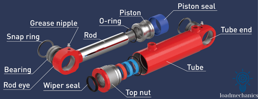
In this detailed engineering breakdown of hydraulic cylinder components, we will examine the function, design principles, material selection, and failure modes of essential parts such as the cylinder barrel, piston, rod shaft, seals, and more. Understanding how these components interact with other key system elements like the hydraulic control valve and the hydraulic pressure relief valve is crucial for engineers, maintenance technicians, and hydraulic specialists aiming to optimize performance, reliability, and safety.
Hydraulic cylinders are the fundamental actuators in any hydraulic system, converting hydraulic energy into precise linear mechanical force and motion. These actuators play a critical role in diverse applications ranging from industrial automation and construction machinery to aerospace systems and offshore drilling platforms. Whether powered by a central hydraulic unit or an electric hydraulic pump, their performance depends heavily on the integrity and design of each internal component.
Hydraulic Cylinder Components: A Detailed Engineering Breakdown
1. Cylinder Barrel (Tube)
1.1. Function – Structural Role in the Hydraulic System
The cylinder barrel serves as the main pressure vessel in a hydraulic cylinder. It contains the pressurized hydraulic fluid and provides a precise linear path for the piston’s reciprocating motion. Structurally, it must:
- Withstand high internal working and peak pressures without plastic deformation.
- Maintain a smooth, precisely finished internal bore to minimize friction and wear on seals.
- Ensure perfect concentricity with the piston and rod to prevent misalignment, side loading, and seal failure.
1.2. Engineering Considerations
1.2.1. Material Selection
Most hydraulic cylinder barrels are manufactured from seamless carbon steel or alloy steel tubing, such as ST52 or C45, due to their strength, machinability, and cost-effectiveness. In specialized applications, alternative materials are used:
- Stainless Steel (e.g., AISI 316L) – for corrosive or marine environments.
- Fiber-Reinforced Composites – used in weight-sensitive or corrosion-critical systems.
- Internally Chrome-Plated Steel Tubes – enhance wear and corrosion resistance in high-cycle applications.
1.2.2. Internal Surface Finish
To reduce friction and ensure long seal life, the inner surface of the barrel is finished using:
- Skiving and Roller Burnishing – standard process achieving Ra ≤ 0.3–0.4 µm.
- Honing – for higher precision requirements, can achieve Ra ≤ 0.2 µm.
A finely finished surface:
- Reduces dynamic friction between seals and the barrel wall.
- Minimizes wear on piston seals and guide rings.
- Prevents stick-slip motion, improving smoothness in low-speed applications.
1.2.3. Wall Thickness and Stress Calculations
The barrel’s wall thickness is a critical design parameter and is typically determined using classical pressure vessel theory:
t= (PD)/ (2σs×E)
Where:
- P: Working pressure
- D: Internal diameter of the barrel
- σs: Material yield strength
- E: Safety factor (usually 1.5 to 2.5)
Additional factors include:
- Hoop stress (circumferential stress), the dominant stress in thin-walled cylinders.
- Fatigue resistance for cyclic load environments.
- Thermal expansion in high-temperature systems or outdoor applications.
1.3. Common Failures and Issues
1.3.1. Internal Scoring or Pitting
Surface damage inside the barrel is typically caused by:
- Contaminants in the hydraulic fluid, leading to abrasion.
- Seal failure, allowing hard particles to enter the sliding zone.
- Improper material selection or insufficient surface hardening.
Consequences: Increased internal leakage, higher friction, reduced cylinder efficiency.
1.3.2. Corrosion
Corrosion is a common issue in barrels exposed to harsh environments:
- Pitting corrosion leads to localized wall thinning.
- Galvanic corrosion may occur if dissimilar metals are not properly insulated.
Preventative measures include:
- Using corrosion-resistant materials.
- Chrome or nickel plating on internal surfaces.
- Applying epoxy or polymer coatings for chemical protection.
1.3.3. Out-of-Roundness (Barrel Deformation)
Out-of-roundness can develop due to:
- Poor welding practices during fabrication.
- External mechanical shocks (drops, impacts).
- Improper clamping or mounting during maintenance.
Consequences:
- Seal failure due to uneven loading.
- Piston misalignment, leading to asymmetric wear and stroke issues.
- Increased internal leakage and reduced efficiency.
1.4. Technical Summary
| Parameter | Recommended Values / Notes |
|---|---|
| Material | ST52, C45, 316L, Composite |
| Surface roughness (internal) | ≤ 0.4 µm Ra (honed or skived & burnished) |
| Geometric roundness tolerance | ≤ 0.1 mm over full length |
| Typical working pressure | 100–350 bar (application-dependent) |
| Wall thickness (t) | Calculated based on pressure, stress, and safety |
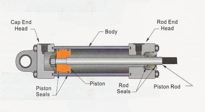
2. Piston – Key Hydraulic Cylinder Components
2.1. Function – Power Transmission in the Hydraulic Cylinder
The piston is a critical internal component responsible for converting hydraulic pressure into linear mechanical force. Located inside the cylinder barrel, it divides the internal space into two pressure chambers and moves in response to differential pressure between them. Key functions include:
- Transmitting force from the hydraulic fluid to the piston rod.
- Maintaining pressure separation between the two chambers.
- Providing a mounting base for piston seals and wear rings.
2.2. Engineering Considerations
2.2.1. Material Selection
The piston must be rigid, wear-resistant, and dimensionally stable. Common materials include:
- Carbon steel (C45, EN8) – standard for most industrial applications.
- Ductile cast iron (e.g., GGG40/50) – used when complex geometries or superior damping properties are required.
- Aluminum alloys – chosen for weight-sensitive mobile hydraulic systems.
- Bronze or brass alloys – used in specialty cylinders requiring non-sparking or low-friction surfaces.
2.2.2. Geometry and Dimensions
- The outer diameter (OD) of the piston is closely matched to the internal diameter of the barrel, allowing precise sealing and minimal clearance.
- The piston thickness and wall structure must ensure rigidity under compression and tension, avoiding deformation under full load.
- Often, pistons feature machined grooves to hold dynamic seals and wear rings.
2.2.3. Seal Retention and Groove Design
Seal grooves are machined with high precision to accommodate:
- Primary pressure seals (e.g., U-cups, O-rings)
- Secondary seals or backup rings (for high-pressure spike protection)
- Wear rings (guide rings) to absorb lateral loads and prevent metal-to-metal contact with the barrel.
Groove design parameters follow international standards (e.g., ISO 5597, ISO 7425) and depend on:
- Seal type and profile
- Expected pressure range
- Material expansion and contraction tolerances
2.3. Key Design Parameters
2.3.1. Pressure Distribution
The piston experiences axial loading on one side from pressurized fluid, and opposing backpressure on the other. Design must account for:
- Maximum operating pressure
- Transient pressure spikes (surge pressure)
- Differential pressure scenarios (especially during regenerative operations)
2.3.2. Leakage and Seal Performance
Even minimal radial play or surface imperfections can cause internal leakage. Engineering considerations include:
- Tight tolerance between the piston OD and barrel ID
- Proper surface finish (typically Ra ≤ 0.8 µm on seal contact surfaces)
- Material compatibility with the hydraulic fluid
2.3.3. Thermal and Mechanical Stress
Pistons operate in a dynamic, high-load environment. Engineering analysis should include:
- Thermal expansion compatibility with seals and barrel
- Fatigue analysis under cyclic loading
- Buckling risk, especially in long-stroke cylinders
2.4. Common Failures and Issues
2.4.1. Seal Extrusion or Blow-Out
Caused by:
- Incorrect seal groove dimensions
- Overpressure beyond rated limits
- Thermal expansion mismatches
Result: Catastrophic internal leakage, loss of cylinder performance.
2.4.2. Galling or Metal-to-Metal Contact
Occurs when:
- Wear rings are missing or improperly sized
- Excessive side loading is present
- Contaminated fluid reduces lubrication
Result: Barrel scoring, increased friction, and heat buildup.
2.4.3. Cracks or Deformation
Common in aluminum pistons under overload or in welded-steel pistons with poor weld quality. Finite Element Analysis (FEA) is often used during design to ensure mechanical integrity under extreme load cases.
2.5. Technical Summary
| Parameter | Typical Value / Notes |
|---|---|
| Material | C45 steel, ductile iron, aluminum alloys, bronze |
| Surface finish (seal contact) | Ra ≤ 0.8 µm |
| Piston-barrel clearance | ~0.05 – 0.1 mm depending on size and pressure |
| Groove standards | ISO 5597, ISO 7425 |
| Wear ring width | ~5–10 mm typical (depends on diameter and side load) |
| Max operating pressure | Up to 350 bar (standard); 700+ bar for heavy-duty cylinders |
3. Piston Rod (Rod Shaft)
Function:
The piston rod transmits linear force from the piston to the machine component being actuated.
Engineering Considerations:
- Material: Induction-hardened chrome-plated steel (e.g., C45E or 42CrMo4), often with a chrome, nickel-chrome, or ceramic coating.
- Surface Finish: Highly polished to minimize seal wear (Ra < 0.2 μm).
- Tensile Strength: Designed to handle high compressive and tensile loads.
- Buckling Resistance: Calculated using Euler’s critical load formula.
Common Issues:
- Rod bending due to side loading
- Corrosion leading to pitting and seal damage
- Chrome plating flaking or peeling
4. Rod End / Rod Eye
Function:
The rod end provides the interface between the hydraulic cylinder and the external load. It typically includes clevises, spherical bearings, or threaded rod ends for mechanical linkage.
Engineering Considerations:
- Alignment: Must accommodate slight misalignment via spherical or flexible joints.
- Mounting Types: Clevis, eye, flange, or threaded ends.
- Fatigue Resistance: Especially important in dynamic or cyclic loading applications.
Common Issues:
- Misalignment leading to side loads
- Thread wear or galling
- Bearing failure in pivoting joints
5. Cylinder Head (Gland)
Function:
The cylinder head, also known as the gland or gland cap, retains the piston rod, contains the rod seals, and serves as the front closure of the cylinder barrel.
Engineering Considerations:
- Seal Housing: Accommodates multiple seals (wiper, rod seal, buffer seal).
- Material: Typically steel or cast iron; aluminum in lightweight applications.
- Mounting: Threaded, bolted, or welded to the barrel.
Common Issues:
- Seal groove damage
- Gland nut loosening under vibration
- Premature wear from contaminated fluid
6. Cylinder Cap (End Cap) in Hydraulic Cylinder Components
Function:
The cylinder cap is the rear enclosure of the cylinder barrel. It houses the piston and acts as the backstop for the piston stroke.
Engineering Considerations:
- Mounting Configuration: Flanged, bolted, or threaded.
- Ports: Often includes hydraulic port for fluid entry/exit.
- Integrated Bearings: May contain wear rings or bushings.
Common Issues:
- Leakage at O-ring interface
- Deformation from excessive torque
- Cracking under pressure surges
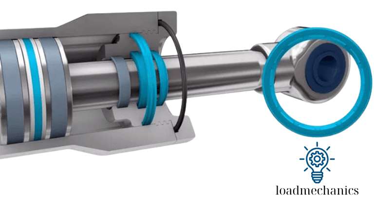
7. Seals and Wipers
Function:
Hydraulic seals ensure that fluid remains within the cylinder, preventing external leakage and internal bypass. Wipers prevent contaminants from entering the cylinder during rod retraction.
Types of Seals:
- Rod Seal: Prevents leakage around the piston rod.
- Piston Seal: Prevents fluid from passing across the piston.
- Buffer Seal: Absorbs pressure spikes and protects the rod seal.
- Wiper Seal: Removes dirt from the rod surface.
Material Selection:
- Nitrile Rubber (NBR): General purpose
- Polyurethane (PU): High abrasion resistance
- Fluorocarbon (FKM): High temperature and chemical resistance
- PTFE: Low friction and high wear resistance
Common Issues:
- Extrusion due to pressure spikes
- Seal hardening or cracking from heat or chemicals
- Improper installation or dimension mismatch
8. Bearing or Wear Rings
Function:
Wear rings guide the piston and rod, maintaining concentricity and preventing metal-to-metal contact, thus reducing wear.
Engineering Considerations:
- Material: Often made of bronze, PTFE-filled composites, or phenolic resin.
- Clearance Fit: Critical to reduce friction while maintaining alignment.
Common Issues:
- Wear ring collapse under excessive load
- Debris embedding into soft materials
- Misalignment causing scoring of rod or barrel
Conclusion Hydraulic Cylinder Components
Hydraulic cylinder components form a precisely engineered system designed to withstand extreme pressure, mechanical shock, and environmental challenges. Each element—barrel, piston, rod, seals, and mounts—must be selected and maintained with care to ensure long service life and reliable performance. By understanding the function, materials, and failure modes of each component, engineers can design more efficient systems and diagnose issues with greater accuracy.