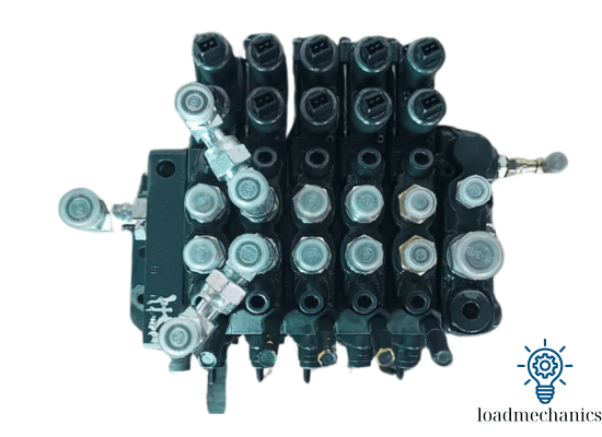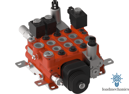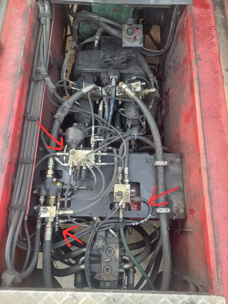
Hydraulic control valve are critical components in any hydraulic system. They help regulate the flow, direction, and pressure of hydraulic fluid, ensuring smooth and precise operation of machinery. In this article, we will explain what hydraulic control valves are, how they work, their main functions, and the most common types used in industrial and mobile applications.
Hydraulic Control Valve Explained: Types, Functions, and How It Works
What Is a Hydraulic Control Valve?
A hydraulic control valve is a mechanically or electrically actuated device that controls the flow characteristics (volume, direction, and pressure) of pressurized fluid (typically oil) in a closed-loop hydraulic circuit.

In practical terms, the hydraulic control valve acts as the “brain” of the system, determining when, where, and how much fluid is directed to various actuators such as hydraulic cylinders, hydraulic motors, or pilot-operated components.
The valve may be manually, electrically, hydraulically, or pneumatically actuated, depending on the system design.
These valves must handle:
High pressures (typically from 160 bar to 350+ bar in industrial systems)
Variable flow rates (liters per minute, often between 5 L/min and 250+ L/min)
High fluid cleanliness requirements (ISO 4406:1999 standard < 18/16/13)
How Does a Hydraulic Control Valve Work?

Hydraulic control valves are the nerve center of any hydraulic system, responsible for managing fluid direction, pressure, and flow rate. The schematic above illustrates a closed-loop electro-hydraulic control system featuring a hydraulic cylinder, pressure feedback, and a directional control valve — the core component controlling actuator behavior.
Working Principle Overview
The hydraulic control valve, labeled in the diagram, is a 4/3 directional control valve (four ports, three positions). In a hydraulic system, its operation is based on shifting a spool to direct the hydraulic flow from the pump to either side of the cylinder, or to the tank. Here’s how it works step by step:
1. Hydraulic Power Generation
The electric motor (M) drives a hydraulic pump.
This pump draws fluid from the tank and pressurizes it.
The pressurized fluid is sent into the hydraulic circuit through the control valve block.
🛠️ Relevant components:
Pump with relief valve (to avoid overpressure)
Check valve ensures one-way flow to the system
2. Spool Control via the Control System
The control system (bottom left) receives real-time pressure feedback from the pressure sensor mounted near the hydraulic actuator.
Based on the required position or force, it sends an electrical signal to the solenoid actuators of the control valve.
The solenoid shifts the spool inside the control valve to one of three positions:
Extend the cylinder
Retract the cylinder
Neutral (center) position — blocking all ports or allowing fluid recirculation
⚙️ Control types:
Manual, solenoid-operated, or proportional spool control.
3. Directional Flow Control
Depending on spool position:
Left Position (Extend Cylinder):
Pressurized oil is directed to the rod-end of the cylinder; the opposite end flows back to tank.
Right Position (Retract Cylinder):
Pressurized oil is directed to the piston-end of the cylinder; the rod-end fluid returns to the tank.
Center Position (Neutral):
All flows are blocked or connected to tank for recirculation, based on valve design (e.g. closed-center, open-center).
📌 Note: The design of the center position significantly affects system energy efficiency and heat dissipation.
4. Feedback and Regulation
The pressure sensor measures load-side pressure and feeds it back to the controller.
The controller compares actual vs desired values and adjusts the spool position accordingly.
In some systems, proportional or servo valves are used for more precise movement.
🔬Key Insights Based on the Diagram:
Component Function
Control Valve (4/3 DCV) Directs flow to either side of the actuator
Pressure Sensor Feedback for closed-loop pressure control
Control System Compares input signal and feedback, sends signal to valve solenoids
Check Valve + Relief Valve Ensures safe and unidirectional flow, protects against overpressure
Actuator (Hydraulic Cylinder) Converts hydraulic energy into linear motion (push/pull the load)
💡 Summary:
The hydraulic control valve is not just a flow director — it is a dynamic element that reacts to feedback, maintains control under varying loads, and interfaces with electronic control logic to achieve precision actuation. In the diagram provided, it sits at the heart of a servo-assisted hydraulic drive — an advanced system used in industrial presses, mobile hydraulics, and automation platforms.
🔍 Common Types of Hydraulic Control Valves
The classification of hydraulic valves is typically based on their main function, and they are broadly divided into four primary categories:
1. Directional Control Valves (DCVs)
Directional control valves are responsible for defining the path that hydraulic fluid takes within a system. By switching the flow path between pump, actuator, and tank, DCVs are directly responsible for controlling actuator motion, such as the extension and retraction of a hydraulic cylinder or the rotation of a motor.
- Control the path of fluid flow.
- Available in 2-way, 3-way, and 4-way designs.
- Common configurations: spool valves, rotary valves, and poppet valves.
DCVs are at the heart of most hydraulic systems and must be sized correctly for flow capacity (measured in LPM or GPM) and pressure ratings. They are typically integrated with feedback sensors in modern electro-hydraulic setups.
2. Pressure Control Valves
These valves are crucial for maintaining the stability and safety of a hydraulic system. Pressure control valves ensure that pressure stays within a desired range and prevent damage due to pressure spikes or load variations.
- Maintain system pressure or limit excessive pressure.
- Types include:
- Relief Valves
- Pressure-Reducing Valves
- Sequence Valves
- Counterbalance Valves
These valves directly influence the performance, precision, and protection of hydraulic components and are often paired with pressure sensors for closed-loop control.
3. Flow Control Valves
Flow control valves are used to regulate the speed of actuators by controlling the volumetric flow rate of hydraulic fluid. The speed of a hydraulic cylinder or motor is directly proportional to the flow rate it receives, making these valves essential for speed regulation.
- Regulate the speed of actuators.
- Includes needle valves, orifice valves, and compensated flow control valves.
4. Proportional and Servo Valves
These are high-performance electrohydraulic valves that integrate electrical signal processing with precise mechanical motion control. Used primarily in automation, robotics, metal-forming, and aerospace, these valves allow variable control of flow and pressure, enabling advanced closed-loop systems.
Operated electronically for automation and feedback control.
Used in advanced systems for precise flow and pressure control.
Applications of Hydraulic Control Valves

Hydraulic control valves are indispensable across a wide range of industrial and mobile hydraulic applications. In manufacturing systems, directional control valves operate hydraulic presses, injection molding machines, and robotic actuators by controlling the movement of cylinders and motors. Pressure control valves are critical in systems requiring pressure stability such as CNC machines, where consistent clamping force is essential.
In construction and heavy machinery, like excavators and cranes, flow control valves are used to regulate arm or boom movement, ensuring smooth and safe operation under variable load conditions. Counterbalance valves in lifting equipment prevent free fall of loads, especially in vertical lifting systems.
Mobile hydraulics—including agricultural tractors, forklifts, and mining vehicles—frequently utilize proportional valves for adaptive response to operator input or terrain conditions. Servo valves find their place in aerospace and automated testing setups, where ultra-precise positioning and rapid response to feedback are critical.
Moreover, modern hydraulic power units (HPUs) often integrate all three control valve types (directional, pressure, and flow) to enable modular, automated control of complex systems. The reliability and precision provided by these valves make them a backbone of industrial fluid power systems worldwide.